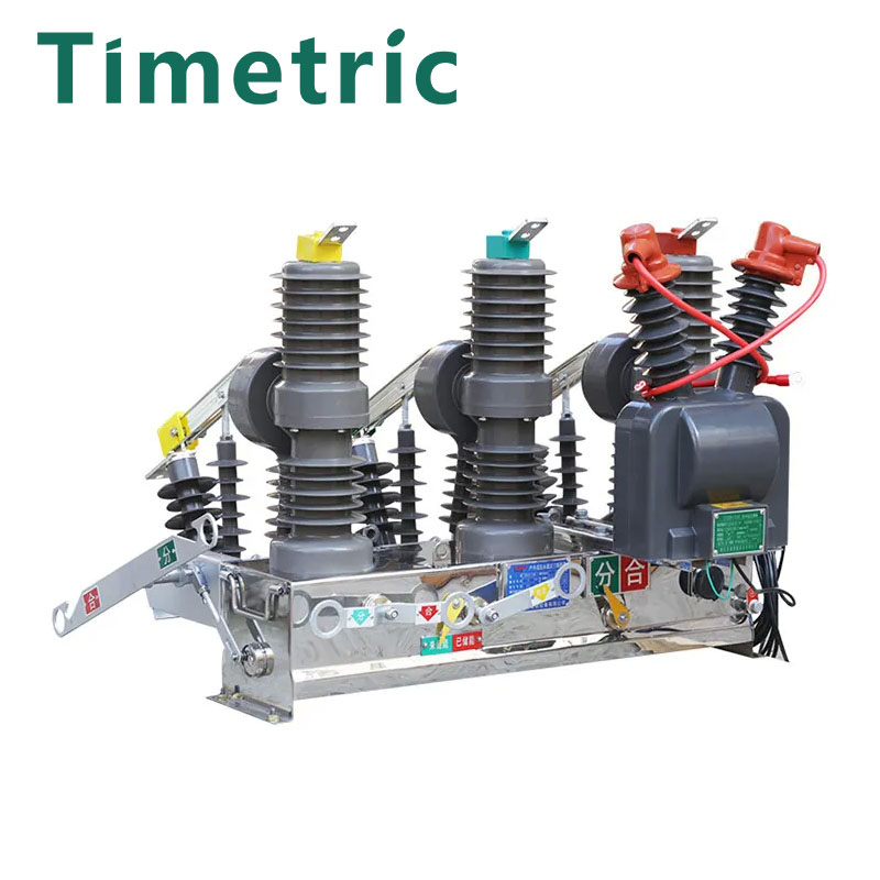
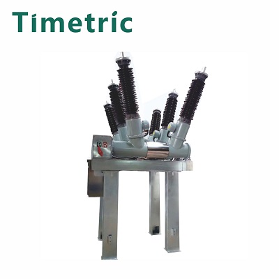
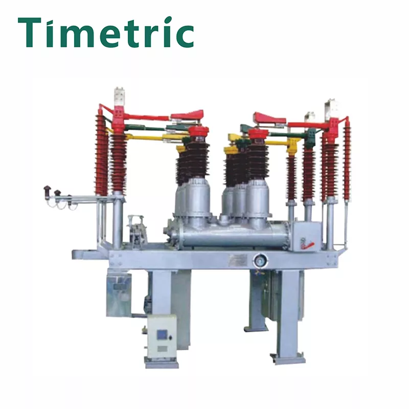
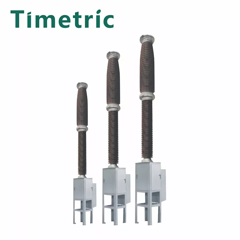
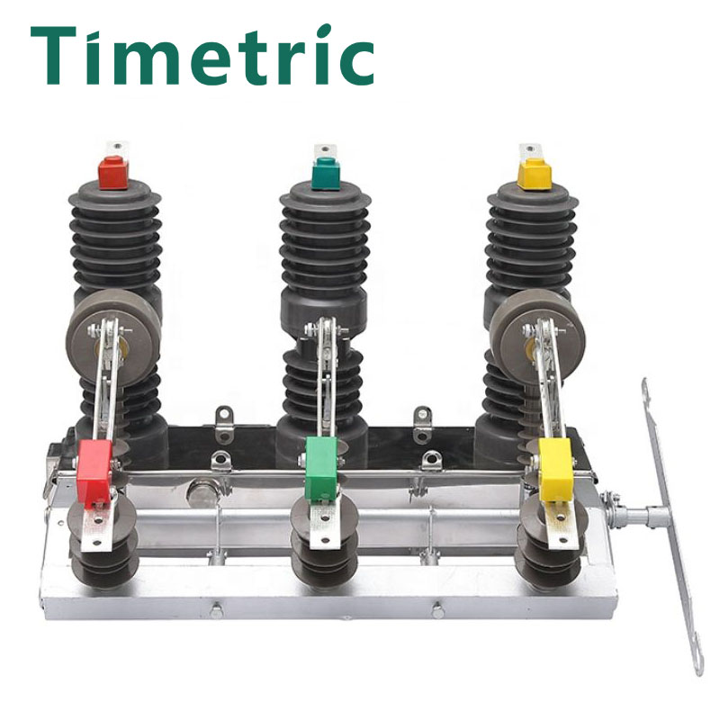
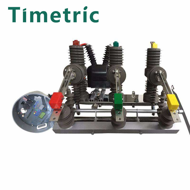
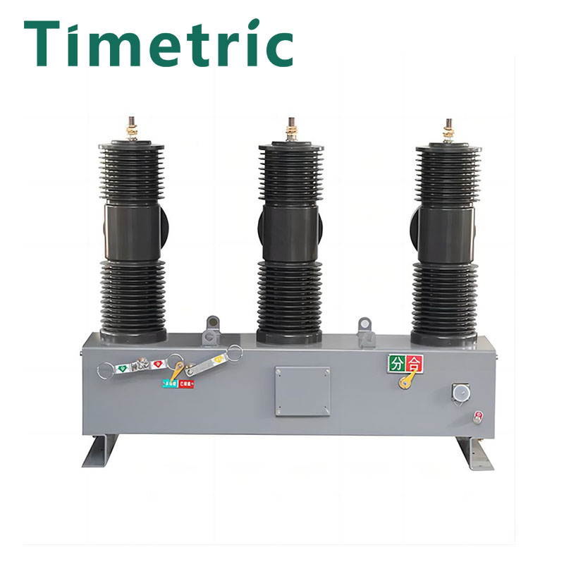
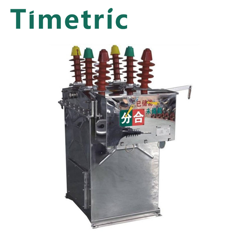
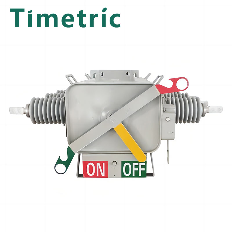
Medium Voltage Outdoor Automatic Circuit Recloser
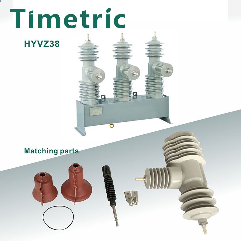
Timetric Electric is a large Medium Voltage Outdoor Automatic Circuit Recloser medium voltage outdoor recloser in China. We have been focusing on outdoor switchgear for many years, and our products are competitively priced and favored by customers in South America, the Middle East, Africa and Southeast Asia. We are committed to providing quality services to customers in these regions.
Send Inquiry
Packing and Transport
The Medium Voltage Outdoor Automatic Circuit Recloser is packed in standard export wooden case along with control unit and components, like connecting cable and terminal connector, etc. Optional accessories like auxiliary power voltage transformer and mounting bracket, etc. will be transported in a separate case. The factory assembled recloser is turned in “Contact OPEN” position to be packed.
Documents provided with the recloser during dispatch: Instruction Manual, Routine Test Certificate, Drawings, Packing List and Other Documents as Mutually Agreed in Contract with Timetric.
The recloser shall be transported in packed condition only. While lifting the wooden case, following precautions must be taken: Ensure that packing cases are not placed on wet surfaces/waterlogged areas; Reclosers should be lifted by a lifting device equipped with forks or slings. If a crane is used, slings shall be used. The units must not be rolled or dropped. Each recloser is assembled and tested at the factory. Prior to shipment, the equipment is thoroughly inspected to ensure a quality product free from defects. If damage is noticed, please contact us.
Storage
The recloser with complete packing should always be stored indoor to protect from direct sunlight, rain or snow. The recloser should be stored in its original transport units, where they are well protected from damage.
Reclosers can be stored up to 3 months from the date of shipment from factory. For longer storage, package needs to be removed and the recloser is kept under required environmental conditions as below:
- Leak Proof Roof
- Solid, Flat Ground
- Relative Humidity Less Than 50%
- Temperature 20℃(+10℃)
- The heating elements must be connected to the electric supply to
protect the control equipment from corrosion or freezing damage. Structures can be stored outdoors with proper care to avert any water accumulation or soil deposition. Spare parts should be stored indoor in their original packing.
Installation
The recloser is suitable to be mounted in a substation frame, double pole frame, single pole frame or in a customized frame according to customer’s needs. No matter what the method is, the recloser should be securely fastened. Follow your company guidelines and various codes for setting the height of the recloser, securing the frame to pole or base, and completing connections. Before leaving factory, every single recloser switch unit is tested as a system in factory with a particular control unit. Therefore, the switch unit and the control unit are matched in the same packing, and if you need to replace the switch unit or the control unit, please contact us.
All metal mounting frames and structures must be commonly grounded to the grounding grid at site. For the electronic components to work well, it is essential that the total impedance of the grounding grid at site is less than one Ohm. Check all grounding connections to the welded earth terminal inside the control box to ensure they are all intact and secured. Do not bend the cable below a radius of 12 inches to avert damage to itself.
Tests Before Mounting
Vacuum Interrupter Test
It is advised to conduct one minute power frequency voltage withstand test on each vacuum interrupter to verify if there is any loss of vacuum during transportation or handling. According to general standard, a vacuum interrupter with intact vacuum seal should be able to withstand 80% of the rated voltage, like 40kV AC (80% of 50kV) for 15kV and 27kV, 56kV AC(80% of 70kV) for 38kV across open contacts. The same interrupter with leaked vacuum (open to normal atmosphere) will flashover at the gap at a much lower voltage. If internal flashover occurs, isolate the phases, and test each phase respectively to identify the defective interrupter. No defective pole assembly is allowed to be put into service and prior to the installation of recloser, ensure all pole assemblies are in good conditions.
Contact Resistance Test
Close the recloser through controller and associated connecting cable. Measure contact resistance with certain equipment rated not less than 100A DC. The value of the contact resistance for each phase should be under 50 micro-ohms. Make sure the contacts of measurement kit are connected across the incoming & outcoming terminal of the pole only.
Mounting
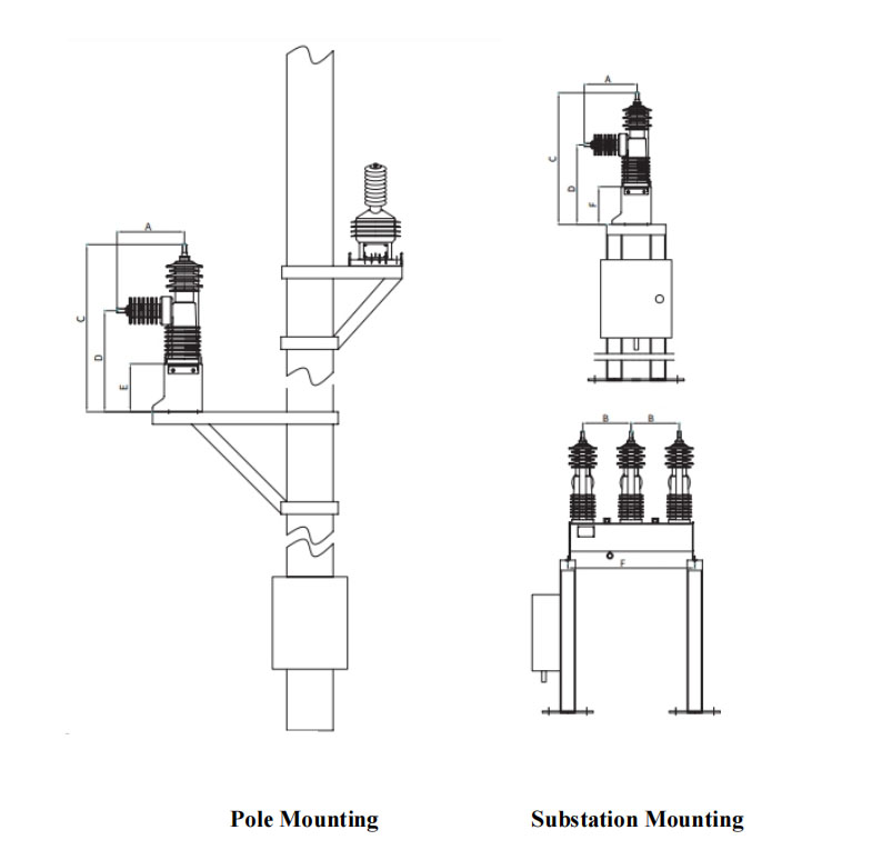
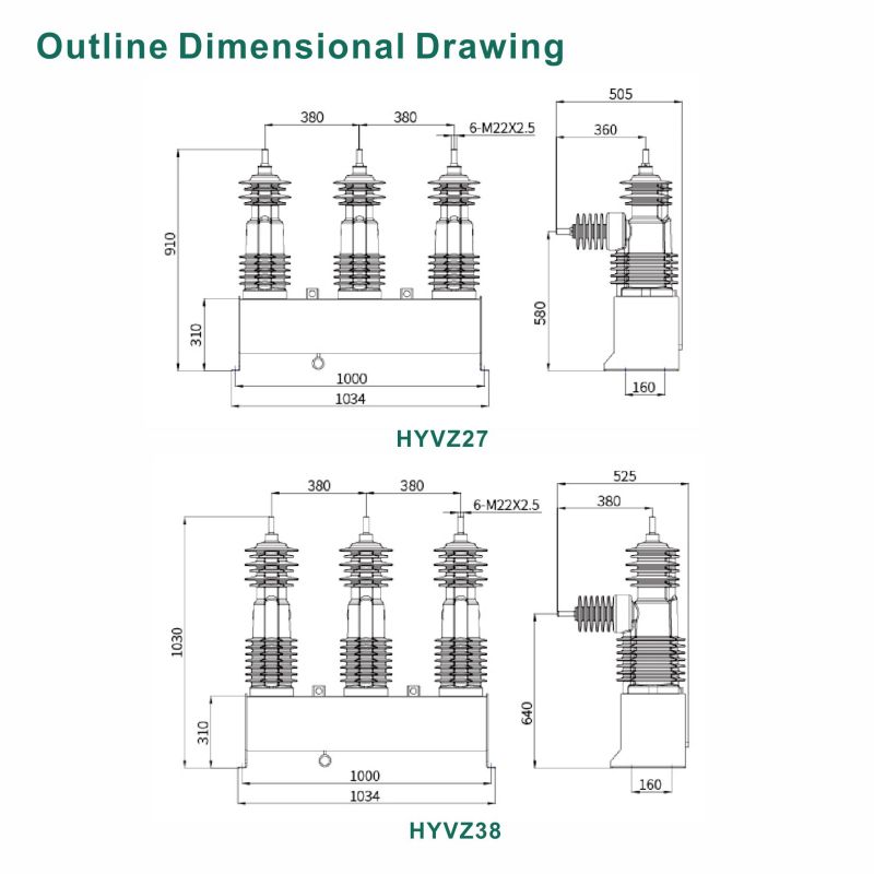
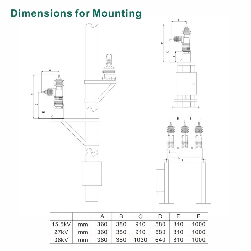
| Model | Unit | A | C | E | F | ||
| 15kV | mm | 360 | 380 | 910 | 580 | 310 | 1000 |
| 27kV | mm | 360 | 380 | 910 | 580 | 310 | 1000 |
| 38kV | mm | 360 | 380 | 1030 | 640 | 310 | 1000 |
Inspections Before Use
The recloser should be tested for mechanical and electrical operation before it is put into service. Please note that the recloser is transported in OPEN(OFF) status when leaving from the factory.
Do not ground either side of the battery, nor attach ground to the terminals of the actuator operating coils. This will result in permanent damage to the unit.
When the recloser is mounted completely with all mechanical and electrical connections accomplished, carry out the following mandatory inspections before energizing the recloser on the main lines:
1. Make sure the recloser is properly leveled and securely anchored.
2. Check the tightness of all hardware to avoid any omission.
3. Check to ensure all wire and cable connections are in perfect mood.
4. Ensure both switch unit and control unit are grounded as mentioned.
Operation
1 Overview of Recloser
The remotely controlled and monitored Recloser:
• Three vacuum interrupters are ganged operated by a single magnetic actuator for both opening and closing.
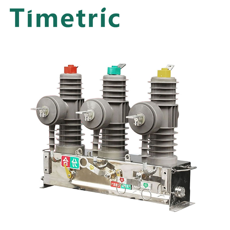
• The actuator and associated mechanism is enclosed in a stainless steel tank and lid, both of which are powder painted for outdoor use.
• The hydrophobic cyclo-aliphatic epoxy resin casting assemblies are bolted to the lid.
• An exterior pointer, conspicuously visible on the tank, indicates the OPEN/CLOSED status of the recloser.
• Operation of the recloser is via low voltage magnetic actuator activated by closing and opening capacitors housed in the controller which in turn are charged by the onboard power supply. Two 12V 7Ah sealed lead acid batteries comprise the backup power supply system to provide system voltage of 24V
Features of Recloser
▶ Robust Encapsulation of Vacuum Interrupter
Adopting whole shaped technology, the interrupters are encapsulated with Premium Hydrophobic Epoxy Resin in high thickness, ensuring the outstanding dielectric characteristic.
▶ Line Voltage Sensing
The recloser senses the line voltage on the lower terminals, which enables voltage measurement, power measurement, directional blocking and different protection protocols.
▶ Current Measurement
Each phase has a Current Transformer(CT) encapsulated on the outcoming side. This enables current measurement on these phases.
▶ Manual Tripping and Lockout Operation
The tank of the recloser is equipped with a manual lever that can be operated from ground level by a hook stick which carry out tripping and lockout simultaneously. This mechanically manual lever inhibits electronically remote closing and the manual tripping ring in down position can only be recovered physically.
Major Operations of Recloser
Following are the descriptions about major operations of Recloser.
▶ Closing
Recloser can be closed only electrically. With controller in LOCAL mode, the recloser can be closed from “I” push button on the front panel. If proper remote connection is established, the recloser can also be closed from remote SCADA via communication, with controller in REMOTE mode. For safety consideration, recloser is not allowed to be manually closed and does not have any separate provision to close the recloser manually using any hook stick.
▶ Opening
Recloser can be opened mechanically as well as electrically. With controller is in LOCAL mode, the recloser can be opened from the “O” push button on the front panel. If proper remote connection is established, the recloser can also be opened from remote SCADA via communication, with controller is in
REMOTE mode.
▶ Manual(Mechanical) Opening
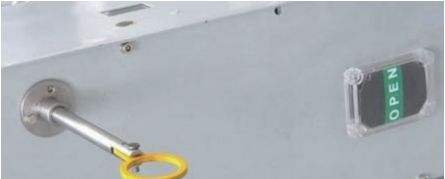
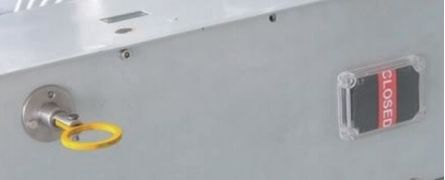
When some emergencies happen, normal opening of the recloser main contacts by controller is not possible, like control box door is locked, or electrical opening is disabled, the switch unit can be safely opened mechanically resorting to a physical way by a standard insulated hook stick from ground level. Manual opening can be achieved by quickly and firmly pulling down the manual trip lever(yellow ring) on the bottom of the tank. This will mechanically open the three poles simultaneously. Recloser has a safe and secured manual trip mechanism.
When the recloser is opened manually, the manual trip lever keeps locked in and blocks any further closing operation of the recloser (CLOSED BLOCKED). Such a situation of manual opening the recloser can most likely be an emergency situation, it is to be ensured that the recloser can not be closed back electrically if it is manually opened for safety consideration.
To ensure recloser stays open, a provision is made inside the recloser that no electrical closing command can be initiated from the control unit locally or remotely. Moreover, to guarantee additional safety, Recloser switch unit remains mechanically locked even if electrical command is forced from the control unit. After the emergency situation ends, to recover operation of closing, it is mandatory to reset the manual trip lever physically to its normal position. Use hook stick to manually return the lever back.
Maintenance
1 Overview of Maintenance
The recloser will be almost maintenance free if it is handled properly. Frequency of operation and local environmental conditions are primary concerns for making up maintenance schedule.
To a large extent, the safety and successful functioning of any device or system connected with the recloser depends on the proper installation, commissioning, programming and configuration of the unit.
To provide long, reliable service, the recloser should be inspected at regular intervals. Operating experience, environmental conditions, the number of operations, the magnitude of current interrupted and any unusual service conditions should be considered in formulating a maintenance schedule.
The maintenance work can only be carried out by professional personnel who has been trained to be familiar with all procedures and regulations.
If needed, please contact Timetric for aid in service performance, maintenance and repair work.
2 Preparations before Maintenance
1. Follow all operation rules as mentioned in previous clauses.
2. Disconnect the power supply from both sides of the switch unit.
3. Ensure that the main circuit is properly earthed.
4. Ensure that all safety norms are followed in your country.
3 Recommended Inspections and Maintenance Plan
Below are some inspections and tests suggested, and based on the results obtained during the periodic inspections, users can set the optimal time interval for carrying out maintenance work.
Visual Inspections:
● Cleanliness of pole terminals
● Damage and tightness of connections, like bents and breaks
● Visible corrosion or damage to metal parts and cables
● All connections of metal parts, like nuts, bolts, hardware etc
● All grounding connections
● All nameplates, rating plates, labels
● All wire connections
Recommended interval of maintenance for installations in normal environment is 18 months, while in extreme environment it is recommended 12 months.
Function Tests:
● Battery general condition and terminals (6 months in normal environment, 6 months in extreme environment)
● Operation of communication modules(if applicable) (6 months in normal environment, 6 months in extreme environment)
● Protection test using secondary injection equipment, in conjunction with recloser function test (4 years in normal environment, 2 years in extreme environment)
● Operation of manual trip lever(yellow ring) (1 year in normal environment, 1 year in extreme environment)
● Battery Replacement, on the basis of frequency and duration of external auxiliary supply failures and extent of battery discharge during such conditions. (3-5 years in normal environment, 3-5 years in extreme environment)
Technical Details
| No. | Technical Specifications | 15kV | 27kV | 38kV |
| 1 | Installation | Outdoor, Pole and Substation Mounting | ||
| 2 | Standard | IEC 62271-111 and IEEE C37.60 | ||
| 3 | Rated System Voltage | 15kV | 27kV | 38kV |
| 4 | Rated Frequency | 50/60Hz | 50/60Hz | 50/60Hz |
| 5 | Rated Continuous Current | 630/800A | 630/800A | 630/800A |
| 6 | Rated Short-Circuit Breaking Current | 12.5kA | 12.5kA | 16kA |
| 7 | Rated Short-Circuit Making Current | 31.5kA | 31.5kA | 40kA |
| 8 | Short Time Current Withstand in 3 sec | 12.5kA | 12.5kA | 16kA |
| 9 | Rated Lightning Impulse Withstand Voltage | 110kV | 125kV | 170kV |
| 10 | Rated Short Duration P.F Withstand Voltage | 50kV | 60kV | 70kV |
| 11 | Line Charging Current | 2A | 5A | 5A |
| 12 | Cable Charging Current | 10A | 25A | 40A |
| 13 | Reclosing Sequence | O - 0.2 s - CO - 2 s - CO - 2 s - CO - Lockout | ||
| 14 | Closing Time | ≤ 60 ms | ≤ 60 ms | ≤ 60 ms |
| 15 | Opening Time | ≤ 40 ms | ≤ 40 ms | ≤ 40 ms |
| 16 | Number of Operations at Rated Current | 15000 times | 15000 times | 15000 times |
| 17 | Insulating Material of Poles | Hydrophobic Epoxy Resin | ||
| 18 | Type of Operating Mechanism | Permanent Magnetic Actuator | ||
| 19 | Creepage Distance | 960 mm | 960 mm | 1290 mm |
| 20 | Clearance, Phase to Phase | 320 mm | 320 mm | 320 mm |
| 21 | Minimum Clearance, Phase to Earth | 270 mm | 270 mm | 350 mm |
| 22 | Impedance between Connections | < 50 μΩ | < 50 μΩ | < 50 μΩ |
| 23 | Mass of Recloser Excluding Mounting Frame | 140 kg | 140 kg | 155 kg |
| 24 | Protection Class for Switch Unit & Control Unit | IP56 | IP56 | IP56 |
| 25 | Wind Withstand Speed Up to | 200 km/h | 200 km/h | 200 km/h |
| 26 | Ambient Temperature | -40℃ to +55℃ | -40℃ to +55℃ | -40℃ to +55℃ |
| 27 | Altitude | < 4000 m | < 4000 m | < 4000 m |
For use in extreme conditions, like high latitude, high altitude, torridity,
humidity, raininess, frigidity etc, please contact us for technical support.


